Reducers

Send Inquiry

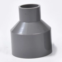
Overview of Reducers

Reducers​ are precision-engineered piping components designed to seamlessly connect pipes of different diameters, ensuring efficient flow transition and system integrity in industrial piping networks. These critical fittings are primarily utilized to reduce or expand the line size, optimizing fluid dynamics and pressure characteristics within the system. Available in two main configurations—concentric reducers​ and eccentric reducers—these components serve distinct functions based on specific application requirements. Concentric reducers maintain a common centerline, creating a symmetrical transition ideal for vertical piping, while eccentric reducers feature offset centerlines to prevent fluid accumulation and vapor trapping in horizontal installations .
Manufactured in compliance with international standards including ASME B16.9, reducers are produced in various materials such as carbon steel, stainless steel, and specialty alloys to withstand diverse operational conditions including extreme temperatures, corrosive media, and high-pressure environments. With applications spanning chemical processing plants, water treatment facilities, oil and gas pipelines, and industrial manufacturing systems, reducers ensure optimal performance while maintaining structural stability and flow efficiency. Their robust construction guarantees a service life matching the pipeline system, with minimal maintenance requirements under standard operating conditions .

Key Features of Reducers

Flow Transition Efficiency

Reducers are engineered to provide smooth flow transition​ between pipes of different diameters, minimizing turbulence and pressure drop within the system. The gradual diameter change in quality reducers ensures minimal energy loss during fluid transmission, contributing to overall system efficiency. This characteristic is particularly valuable in pumping systems where energy conservation is a priority .

Material Versatility and Compatibility

Available in various materials including carbon steel, stainless steel, and specialty alloys, reducers can be selected to match specific application requirements regarding strength, corrosion resistance, and temperature tolerance. This material adaptability ensures compatibility with diverse media including water, chemicals, hydrocarbons, and abrasive slurries, making reducers suitable for virtually any industrial application .

Pressure Integrity and Structural Stability

Reducers maintain pressure integrity​ during diameter transitions, preventing weak points that could compromise system safety. Their structural design ensures even stress distribution, eliminating potential failure points under pressure fluctuations or temperature variations. This reliability is critical in high-pressure applications common in oil and gas and chemical processing industries .

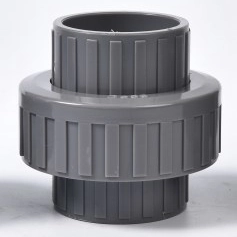
Installation Flexibility

The availability of both concentric and eccentric configurations provides installation flexibility​ to address various piping scenarios. This adaptability allows engineers to select the optimal reducer type based on orientation, flow characteristics, and space constraints, ensuring proper functionality in any installation context .

Types of Reducers and Their Applications
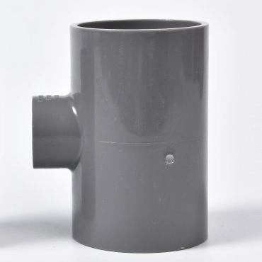
Concentric Reducers

Concentric reducers​ feature a symmetrical design with a common centerline through both ends of the fitting. This configuration is primarily used in vertical piping systems​ where air entrapment is not a concern. The symmetrical reduction ensures even flow distribution, making it ideal for applications where fluid direction is primarily vertical. These reducers are preferred when maintaining a uniform centerline is critical to system design, particularly in pipe racks where consistent bottom of pipe (BOP) elevation is required across supports .

Eccentric Reducers

Eccentric reducers​ feature offset centerlines, creating a flat surface on either the top or bottom of the fitting. This design is crucial in horizontal piping systems​ where drainage or vapor prevention is necessary. When installed with the flat side on top (FOT), they prevent air pocket formation at pump suctions, while flat side on bottom (FOB) installation facilitates complete drainage. This functionality makes them essential in pump suction lines, hydrocarbon pipelines, and systems handling slurries or viscous fluids where vapor locking or sediment accumulation could cause operational issues .

Typical Applications of Reducers

Pump Suction and Discharge Lines

Reducers are critical components in pump piping configurations, particularly at suction inlets​ where proper fluid approach velocity is essential for pump performance. Eccentric reducers installed with flat side up prevent vapor accumulation that could lead to cavitation. On discharge sides, reducers gradually increase velocity while reducing pressure turbulence, enhancing overall system efficiency and equipment longevity .

Pipeline Size Transition

In long-distance pipelines, reducers facilitate systematic diameter changes​ to accommodate varying flow rates or pressure requirements. This application is common in water distribution networks, oil and gas transmission lines, and industrial process piping where flow characteristics change throughout the system. Proper reducer selection ensures minimal energy loss during these transitions .

Pipe Rack Installations

In industrial pipe racks supporting multiple pipelines, eccentric reducers​ maintain consistent bottom of pipe (BOP) elevation across support points when pipe sizes change. This configuration ensures proper load distribution and structural stability while facilitating thermal expansion management. The flat-bottom design provides stable seating on support structures, preventing movement or stress concentration .

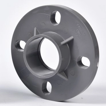
Process Equipment Connections

Reducers provide optimal connections between process equipment and main piping systems, accommodating nozzle size variations​ while maintaining flow characteristics. This application is critical in heat exchangers, vessels, tanks, and other process equipment where inlet/outlet sizes differ from connecting piping. Proper reducer selection prevents turbulence and pressure drop at these critical junctions .

Technical Specifications
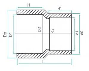
Table: Standard Reducer Specifications
Parameter
Specification Range
Standards
Types
Concentric, Eccentric (Flat on Top/Flat on Bottom)
ASME B16.9
Size Range
1/2″ to 48″ (custom sizes available)
Industry standards
Material Options
Carbon Steel, Stainless Steel, Alloy Steel, PVC, CPVC
Material-specific certifications
Pressure Rating
150# to 2500# (standard)
ASME pressure classes
Temperature Range
-20°F to 1000°F (material dependent)
Application-specific
Connection Types
Butt weld, Socket weld, Threaded
ASME B16.9, B16.11
Standards Compliance
ASME, ANSI, ISO, DIN
International standards

SIZE D1 D2 H d1 d2 H1 L
DN20X15 25.3 31.9 19 20.3 26.3 16.5 40
DN25X15 32.35 39.5 22.5 20.3 26.3 16.5 47.8
DN25X20 32.35 39.5 22.5 25.3 31.9 19 47.4
DN32X20 40.4 49.8 26.5 25.3 31.9 19 56.6
DN32X25 40.4 49.8 26.5 32.35 39.95 22.5 54.8
DN40X15 50.45 62 31.5 20.3 27 16.5 66
DN40X20 50.45 62 31.5 20.3 31.9 19 66
DN40X25 50.45 60.25 31.5 40.4 49.8 26.5 67
DN40X30 50.45 75 38 40.4 49.8 26.5 65.1
DN40X32 63.5 75.9 38 25.3 31.9 19 79
DN40X25 63.5 75.9 38 32.35 39.95 22.5 80
DN40X32 63.5 75.9 38 40.4 49.8 26.5 80
DN40X40 63.5 75.9 38 50.45 60.25 31.5 77.7
DN40X25 75.5 88.91 44 32.35 39.95 22.5 93.5
DN40X20 75.5 88.91 44 25.3 31.9 19 92.5
DN40X30 75.5 88.91 44 50.45 60.25 31.5 93.5
DN40X32 75.5 88.91 44 43.5 51.9 38 125.5
DN40X25 90.55 105.15 51.5 32.35 39.95 22.5 108
DN40X50 90.55 105.15 51.5 63.5 75.9 38 108
DN40X65 90.55 105.15 51.5 75.5 88.91 44 107.3
DN100X50 110.6 127.39 61.5 63.5 75.9 38 128
DN100X65 110.6 127.39 61.5 75.5 88.91 44 128.6
DN100X80 110.6 127.39 61.5 90.55 105.15 51.5 127.4
DN125X50 140.6 161.4 76 90.55 105.15 61.5 138.3
DN125X80 140.6 161.4 76 110.6 127.39 61.5 137.7
DN150X100 160.7 184.5 86.5 110.6 127.39 61.5 180.2
DN150X125 160.7 184.5 86.5 140.6 161.4 76 177.3
DN200X115 200 228.1 106.2 110 127.5 61.5 217
DN200X160 200 228.1 106.2 160 184.9 86.5 217
DN200X100 226.2 253.8 118.5 110.6 127.39 61.5 244.5
DN200X150 226.2 253.8 118.5 160.7 184.5 86.5 242.5
DN200X200 226.2 283.8 131.5 160 184.9 86.5 270
DN200X225 200 263.4 131.5 226 253.8 118.5 270
DN200X225 281.5 315.5 149 226.2 253.8 118 304
DN280X160 281.5 315.5 149 160.8 185 85 304
DN315X225 316.7 355 166 226.2 253.8 118 355
DN315X160 316.7 355 166 160.8 185 85 355
DN355X135 356.8 395 186 316.7 355 162 385
DN355X225 356.8 395 186 226.2 253.8 118 385
DN400X135 400 442 208 316.7 355 162 440
DN400X160 402 442 205 356.8 395 162 440

Frequently Asked Questions (FAQs)

Q1: When should I use a concentric reducer versus an eccentric reducer?
Concentric reducers​ are typically used in vertical piping systems where drainage is not a concern, as they maintain a uniform centerline. Eccentric reducers​ are essential in horizontal piping where vapor prevention or complete drainage is required—use flat side up (FOT) for air elimination at pump suctions and flat side down (FOB) for drainage applications .
Q2: How does reducer selection impact pump performance?
Proper reducer selection significantly affects pump performance and longevity. Eccentric reducers installed with the flat side up at pump suctions prevent vapor accumulation​ and subsequent cavitation. The gradual transition maintains optimal flow characteristics, ensuring efficient pump operation and reducing maintenance requirements .
Q3: Can reducers be used in both directions of flow?
Yes, reducers can generally accommodate flow in either direction. However, for optimal performance, the orientation should consider flow direction. When used as expanders, a different flow dynamic occurs, but the same fitting can typically serve both functions effectively in most applications .
Q4: What are the key considerations when selecting a reducer?
Key selection factors include flow characteristics, pipe orientation, media properties, pressure/temperature conditions, and space constraints. Additionally, material compatibility with the conveyed media and compliance with relevant standards (ASME, ANSI) are essential for ensuring system integrity and safety .
Q5: How are reducers dimensioned and specified?
Reducers are specified by their larger and smaller end diameters, type (concentric or eccentric), material, wall thickness, and applicable standards. The reducing angle or length is also critical, with gradual transitions preferred for smoother flow. Standard dimensional specifications are provided in ASME B16.9 for reference and selection .
daiwang@skrpipe.com
+86 153-703-27218
Whatsapp