Overview of Slip-On Flange
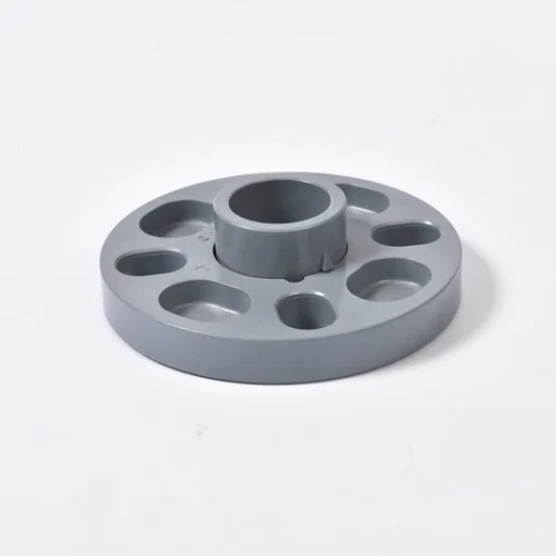
Sikerui Slip-On Flange is a precision-engineered pipe connecting component designed to create secure, leak-proof joints in industrial piping systems by sliding over the pipe end and being secured with fillet welds . Characterized by its distinctive hub design and relatively low profile, this flange type offers exceptional installation flexibility and cost efficiency compared to weld neck alternatives . Manufactured in compliance with international standards including ASME B16.5, ANSI B16.47, and DIN EN 1092-1, slip-on flanges are available in pressure classes from 150 to 2500 and sizes ranging from 1/2″ to 48″ to accommodate diverse application requirements .
Constructed from robust materials including carbon steel, stainless steel, alloy steel, and specialized metals, slip-on flanges maintain reliable performance under temperature extremes from -29°C to +600°C and pressure ratings up to 2500 class . Their double-fillet welding system (inside and outside the flange) ensures structural integrity and leakage prevention, making them ideal for petroleum, chemical processing, water supply, and power generation industries with a service life matching the pipeline system itself .
Key Features of Slip-On Flange
1. Effortless Installation and Alignment
Slip-on flanges feature a simplified installation process that significantly reduces assembly time compared to weld neck flanges. The design allows the flange to easily slide over the pipe end, facilitating quick alignment without requiring precise bevel preparation . This characteristic is particularly valuable in field installations and confined spaces where adjustment flexibility is essential for efficient pipeline assembly .
2. Cost-Effectiveness and Material Efficiency
Slip-on flanges offer substantial cost savings over alternative flange types due to simpler manufacturing processes and reduced material requirements . The absence of an extended neck translates to lower weight and material usage, making them an economically advantageous choice for large-scale projects while maintaining performance integrity for low to medium-pressure applications .
3. Versatile Material Compatibility
Available in numerous material grades including carbon steel (ASTM A105), stainless steel (ASTM A182 F304/316), alloy steels, and specialized metals, slip-on flanges accommodate diverse operational environments from standard water service to corrosive chemical processing . This material adaptability ensures compatibility with various media while providing appropriate corrosion resistance, temperature tolerance, and mechanical strength for specific application requirements .
4. Robust Sealing Performance
The dual fillet weld configuration (inside and outside welding) creates a robust connection that effectively distributes stress and prevents leakage under pressure fluctuations . Available with different face types including Raised Face (RF), Flat Face (FF), and Ring Type Joint (RTJ), these flanges ensure reliable gasket compression and sealing performance across various pressure classes .
5. Adaptability to System Modifications
Slip-on flanges provide exceptional flexibility for system modifications, repairs, and expansions . Their removable nature facilitates easier disassembly and reconfiguration compared to permanent connections, reducing maintenance downtime and enabling efficient pipeline alterations without requiring complete section replacement .
Typical Applications of Slip-On Flange
Oil and Gas Pipeline Systems
Slip-on flanges are extensively employed in petroleum and natural gas pipelines for gathering lines, distribution networks, and refinery connections . Their cost-effectiveness and reliable performance make them suitable for hydrocarbon transport where pressure requirements fall within their design parameters, with appropriate material selection ensuring corrosion resistance in sour service environments .
Chemical Processing Plants
In chemical manufacturing facilities, corrosion-resistant slip-on flanges manufactured from stainless steel or specialized alloys provide secure connections for process piping handling aggressive chemicals . Their ease of installation and maintenance accessibility supports efficient operation in complex chemical plants where periodic system modifications are common .
Water Supply and Treatment Facilities
Municipal water systems utilize slip-on flanges for potable water distribution, treatment plant piping, and irrigation infrastructure . The non-toxic properties of appropriately coated or stainless materials ensure water quality compliance, while the flanges’ installation efficiency supports rapid deployment in urban water infrastructure projects .
Power Generation Systems
Power plants employ slip-on flanges in cooling water circuits, fuel supply lines, and auxiliary systems where their pressure capabilities align with operational requirements . The adaptability to various pipe materials and sizes facilitates comprehensive plant piping with consistent connection methodology across different service types .
Industrial Plumbing and HVAC
Commercial and industrial facilities utilize slip-on flanges for mechanical system piping, including heating, ventilation, and air conditioning applications . Their cost-effectiveness and straightforward installation make them practical for large-scale building services where numerous connections are required without extreme pressure demands .
Technical Specifications
Table: Standard Slip-On Flange Specifications
|
|
|
|
|
|
1/2″ to 48″ (DN15 to DN1200)
|
|
|
|
150, 300, 400, 600, 900, 1500, 2500
|
|
|
|
Carbon Steel, Stainless Steel, Alloy Steel, Duplex Steel, Nickel Alloys
|
|
|
|
Raised Face (RF), Flat Face (FF), Ring Type Joint (RTJ)
|
|
|
|
-29°C to +600°C (material dependent)
|
|
|
|
ASME B16.5, ANSI B16.47, DIN EN 1092-1, MSS SP44
|
|
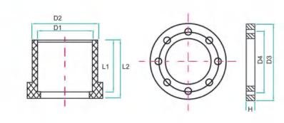
| SIZE |
Number |
D1 |
D2 |
H |
L1 |
L2 |
D3 |
r-φ-e |
D4/BCD |
| DN15 |
HFL15 |
20.3 |
26.3 |
13.1 |
16.5 |
25 |
95 |
4-φ-18 |
65 |
| DN20 |
HFL20 |
25.3 |
31.9 |
14.7 |
19 |
28.5 |
105 |
4-φ-18 |
75 |
| DN25 |
HFL25 |
32.35 |
39.95 |
16 |
22.5 |
31.5 |
115 |
4-φ-18 |
85 |
| DN32 |
HFL32 |
40.4 |
49.8 |
17.5 |
26.5 |
34 |
140 |
4-φ-18 |
100 |
| DN40 |
HFL40 |
50.45 |
60.25 |
18.6 |
31.5 |
38.5 |
150 |
4-φ-18 |
110 |
| DN50 |
HFL50 |
63.5 |
75.9 |
20.3 |
38 |
45 |
165 |
4-φ-18 |
125 |
| DN65 |
HFL65 |
75.5 |
88.91 |
23.6 |
44 |
51.5 |
185 |
4-φ-18 |
145 |
| DN80 |
HFL80 |
90.55 |
105.15 |
26.3 |
51.5 |
60 |
200 |
8-φ-18 |
160 |
| DN100 |
HFL100 |
110.6 |
127.39 |
28 |
61.5 |
70.7 |
220 |
8-φ-18 |
180 |
| DN125 |
HFL125 |
140.6 |
161.4 |
33.2 |
76 |
86 |
250 |
8-φ-18 |
210 |
| DN150 |
HFL150 |
160.7 |
184.5 |
34.1 |
86.5 |
95 |
285 |
8-φ-22 |
240 |
| dn200 |
HFL200 |
200 |
340 |
36 |
106.2 |
113 |
340 |
8-φ-22 |
295 |
| DN200 |
hf1250 |
226.2 |
253.8 |
35 |
118.5 |
130 |
340 |
8-φ-22 |
295 |
| dn250 |
HFL250 |
250 |
395 |
40 |
131.5 |
138.5 |
395 |
12-φ-22 |
350 |
| DN250 |
HFL250 |
281.5 |
314.8 |
41.4 |
147 |
165 |
405 |
12-φ-26 |
355 |
| DN300 |
HFL300 |
316.7 |
344.5 |
41.7 |
165 |
188 |
445 |
12-φ-26 |
400 |
| DN350 |
HFL350 |
356.8 |
386.2 |
45 |
183.5 |
193.5 |
510 |
16-φ-26 |
445-460 |
| DN400 |
HFL400 |
402 |
432.7 |
47 |
208 |
231 |
572 |
16-φ-26 |
495-515 |
| DN250 (PH10) |
HFL250 |
280.6 |
304.7 |
41.4 |
147 |
165 |
405 |
16-φ-26 |
355 |
| DN300 (PH10) |
HFL300 |
315.7 |
341.5 |
41.7 |
165 |
188 |
445 |
16-φ-26 |
400 |
| DN350 (PH10) |
HFL350 |
355.8 |
385 |
45 |
183.5 |
193.5 |
510 |
16-φ-26 |
460 |
| DN400 (PH10) |
HFL400 |
401 |
429.5 |
46 |
208 |
231 |
570 |
16-φ-26 |
515 |
Frequently Asked Questions (FAQs)
Q1: What are the key differences between slip-on flanges and weld neck flanges?
Slip-on flanges feature a simpler design that slides over the pipe and utilizes fillet welds, while weld neck flanges have a tapered hub and require butt welding . This makes slip-on flanges easier to install and more cost-effective for low to medium-pressure applications, whereas weld neck flanges provide superior performance under high stress, vibration, and temperature fluctuation conditions .
Q2: How does the pressure rating of slip-on flanges compare to other flange types?
Slip-on flanges typically have lower pressure ratings than weld neck flanges of equivalent size and material . While suitable for classes 150 through 600 in most applications, weld neck flanges are preferred for higher pressure services above class 600 and severe cyclic loading conditions where enhanced fatigue resistance is required .
Q3: What welding procedures are required for proper slip-on flange installation?
Proper installation requires double fillet welding with one weld at the hub interface and another at the pipe connection point . This dual-weld configuration ensures sufficient strength and leak prevention, with welding procedures following ASME Section IX requirements and specific material considerations to maintain corrosion resistance in stainless and alloy versions .
Q4: Can slip-on flanges be used in high-temperature applications?
Yes, slip-on flanges can accommodate elevated temperatures up to 600°C depending on the material specification . For extreme temperature services, alloy steel versions (e.g., ASTM A182 F11/F22) are available with appropriate pressure de-rating considerations applied according to ASME B16.5 guidelines .
Q5: What are the available sealing face options for slip-on flanges?
Slip-on flanges are manufactured with multiple face types including Raised Face (RF), Flat Face (FF), and Ring-Type Joint (RTJ) configurations . The Raised Face variant is most common for general applications, while RTJ faces provide enhanced sealing for higher pressure services through metal ring gasket compression .